This page has been automatically translate with Google from the Italian language.

CHAPTER II Powersim Study

2.3 Implementation of the dynamic systems: Powersim Study

The characteristics of System dynamics as soon as described they are generate them, but their implementation demands uses it of specific software.
A high different number packages software is available in order to implement system dynamics and, for the development of this thesis the choice has been oriented the package of modellazione Powersim Study.
Powersim Study is an atmosphere of modellizzazione based exactly on science of the dynamic systems.
Powersim allows to model systems - with all their relations of cause and effect, cycles of feedback and delays - in graphical and intuitiva way.
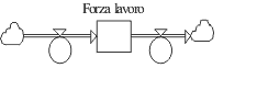
The symbols that represent variable levels, flows and “of aid” (so-called members of the women's army auxiliary corps) are used in order to create graphical rappresentazioni of the system in Manifacturing diagrams (Constructor diagram).
Flows and connections of information represent relations and interconnections. The entire structure of a system, does not import like complex, can be represented in Powersim Study with the use of these variable types of and connections.

2.3.1 Levels and flows

When the simulation of a dynamic system is created, the feedback structures (feedback structures) represent through the use of levels and flows.
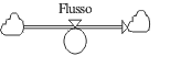
Every element in a feedback cycle, and therefore every element in a system, is or a level or a flow.
The levels are the accumulations in the time while the flows represent activity, movements or variations that modify in the course of the time the levels. The flows fill up or exaust the levels.
This action of the flows that are accumulates to you in levels is the cause of all the dynamic behaviors of the world.
In integrating one function, simply measure the area under the function dividend in sections of equal amplitude and then adding the area of all the sections like illustrated in figure 2.5.
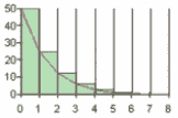
Figure 2.5-When integral one function measure the area under the function same dividend in sections of equal amplitude and then adding the area of all the sections

When a model of graphical simulation in Powersim is created Study, connecting the symbols of the variable ones generate the integral equations (flows). Every variable in the model it is defined from an equation, in the same way with which the cells in a sheet of electronic calculation are defined.
The used simbologia in order to represent levels and flows is following:

The levels are represent to you from cases and indicate the accumulations that they can increase or diminish in the time.
The levels can be only modified through the flows.

The flows are actions or processes that add (afflusso) or embezzle the accumulations in the level. The clouds at the beginnig and to the end of the flow represent the source and the end of the structure.
The cloud symbol indicates infinite amount and marks the border of the model. The flow is represented from the double arrow and the circle on the flow is behaved from outgoing tap that controls the entering flow and.
In the example of figure 2.6 the level is the “measured force-job” in persons, that they are you increase from the “percentage of assumptions " (flow) and diminished from the “percentage of lay-offs” (flow).
Figure 2.6-Un simple graphical model created with Powersim Study

The clouds indicate that in this model it does not interest from where the persons come recruited or where the fired persons go. Those information are beyond the borders of the model.


Top | Summary | < < Previous | Next > >
/en/home.php" TARGET="_blank">>> Home Page <<